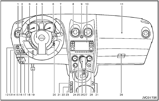
 Nissan Rogue: Instrument panel

Instrument panel
1. Side ventilator
2. Headlight, fog light (if so equipped) and turn signal
switch
3. Steering-wheel-mounted controls (left side)
— Audio control
— Bluetooth® Hands-Free Phone system control
4. Steering wheel
— Horn
— Driver supplemental air bag
5. Meters and gauges
6. Steering-wheel-mounted controls (right side)
— Cruise control switches
7. Wiper and washer switch
8. Center ventilator
9. Hazard warning flasher switch
10. Audio system/Navigation system (if so equipped)
— Clock
— Rear view monitor (if so equipped)
— Around viewTM monitor (if so equipped)
11. Front passenger supplemental air bag
12. Outside remote mirror control switch
13. Headlight aiming control (if so equipped)
14. All-Wheel Drive (AWD) LOCK switch (if so equipped)
15. Fuse box cover
16. Vehicle Dynamic Control (VDC) OFF switch
17. Hood release handle
18. Tilting steering wheel lever
19. Parking brake
20. Ignition switch
21. Heated seat switch (if so equipped)
22. ’“Camera” Around viewTM monitor display switch (if so
equipped)
23. Sport mode switch
24. Power outlet
25. Heater/air conditioner control
26. Selector lever
27. Front passenger air bag status light
28. Rear window and outside mirror (if so equipped)
defroster switch
29. Glove box
 Meters and gauges
Meters and gauges
1. Tachometer
2. Vehicle information display
3. Speedometer
4. Warning/indicator lights
5. Engine coolant temperature gauge
6. switch (twin trip odometer
control and ...
See also:
Wheels and Trim—Aluminum or Chrome
Use a soft, clean cloth with mild soap and water to clean the wheels. After rinsing
thoroughly with clean water, dry with a soft, clean towel. A wax may then be applied.
Keep the wheels clean using ...
Voice tutorial
To listen to a tutorial detailing the operation of
the Voice system:
- Briefly press the Voice button to start a
voice session.
- Wait for the tone to sound, then say Voice
tutorial.
Alternative ...
Lumbar Adjustment
Power Lumbar
Eight-Way Power Seat Shown, Four-Way Similar
A. Lumbar Switch
If available, press and hold the front or rear of the switch (A) to increase
or decrease lumbar support. Release the s ...

