Range Rover Evoque: Sitting in the correct position
 The driver
and front seat passenger
must not ride with the seat fully
reclined.
The driver
and front seat passenger
must not ride with the seat fully
reclined.
 Do not adjust
the seat while the
vehicle is moving.
Do not adjust
the seat while the
vehicle is moving.
The seat, head restraint, seat belt and airbags, all contribute to the protection of the user.
Correct use of these components will give you greater protection. Therefore, you should always observe the following points:
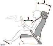
1. Sit in an upright position with the base of your spine as far back as possible and the seatback reclined no more than 30 degrees.
2. Do not move the driver's seat too close to the steering wheel. Ideally, a minimum distance of 254mm (10in) is recommended between the breastbone and the steering wheel airbag cover. Hold the steering wheel in the correct position, with your arms slightly bent.
- Adjust the head restraint so that the top of the head restraint is above the centre line of the head.
- Position the seat belt so that it is mid-way between your neck and your shoulder. Fit the strap tightly across your hips, not across your stomach.
- Ensure that your driving position is comfortable and enables you to maintain full control of the vehicle.
READ NEXT:
 Memory seats
Front seat positions can be saved to vehicle
memory.
Once you have adjusted the power operated
driver’s seat and the exterior mirrors, the
vehicle can memorise the settings for future
use. See
Easy entry/exit
When Easy entry/exit is configured, the driver’s
seat will automatically lower when the ignition
is switched off and the door release lever is
used. Upon returning to the vehicle, when the
drive
Head restraints
Adjust the head restraint so
that the
top of the head restraint is above the
centre line of the head. An incorrectly
adjusted head restraint increases the
risk of death or serious injury in the
SEE MORE:
Double locking
Never double lock the vehicle
with
people, children, or pets inside. In the
event of an emergency they would be
unable to escape and the emergency
services would be unable to release
them quickly.
Double locking secures the vehicle and
prevents the doors being opened from inside
or outsid
Control Diagram, System Operation
Control Diagram
NOTE: A = Hardwired; D = High Speed CAN Bus; O = Local Interconnect
Network (LIN) Bus
CONTROL DIAGRAM - SHEET 1 OF 2
Battery
Starter motor fuse
Battery Junction Box (BJB)
Starter motor
Generator
Transmission Control Module (TCM)
Cooling fan control module
Air Conditioning
