 Dodge Nitro: Four-wheel drive operation
MP 143 Single-Speed Part-Time Transfer Case
Operating Information/Precautions
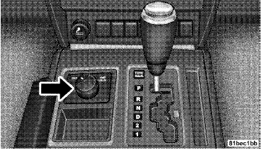
The transfer case is operated by the transfer case switch (located on the center console).
 Transfer Case Switch
The electronically shifted transfer case provides two
mode positions:
• Two-wheel drive high range (2WD).
• Four-wheel drive high range (4WD LOCK).
The electronically shifted transfer case is designed to be driven in the two-wheel drive position (2WD) for normal street and highway conditions (dry hard surfaced roads). When additional traction is required, the transfer case 4WD LOCK position can be used to lock the front and rear driveshafts together and force the front and rear wheels to rotate at the same speed. This is accomplished by rotating the transfer case switch to the desired position. Refer to “Shifting Procedure” for specific shifting instructions. The 4WD LOCK position is designed for loose, slippery road surfaces only.
CAUTION:
• Driving in the 4WD LOCK position on dry hard
surfaced roads may cause increased tire wear and
damage to the driveline components.
• Do not attempt to make a shift while only the front
or rear wheels are spinning. Shifting while only
the front or rear wheels are spinning can cause
damage to the transfer case.
Proper operation of four-wheel drive vehicles depends on tires of equal size, type and circumference on each wheel. Any difference in tire size can cause damage to the transfer case. Tire rotation schedule should be followed to balance tire wear. Since four-wheel drive provides improved traction, there is a tendency to exceed safe turning and stopping speeds. Do not go faster than road conditions permit.
Shifting Procedure – Electronically Shifted Transfer Case
NOTE: If any of the requirements to select a new transfer case position have not been met, the transfer case will not shift. The “4WD Indicator Light” (located in the display under the tachometer) will flash until all the requirements for the selected position have been met. To retry a shift, return the control knob back to the original position, make certain all shift requirements have been met, wait five seconds and try the shift again.
2WD⇔ 4WD LOCK
Rotate the transfer case switch to the desired position. Shifts between 2WD and 4WD LOCK can be done with the vehicle stopped or in motion. With the vehicle in motion, the transfer case will engage/disengage faster if you momentarily release the accelerator pedal after turning the switch. If the vehicle is stopped, the ignition key must be in the ON position with the engine either RUNNING or OFF. This shift cannot be completed if the key is in the ACC position.
NOTE:
• The four-wheel drive system will not allow shifts
between 2WD/4WD LOCK if the front and/or rear
wheels are spinning (no traction). In this situation, the
“4WD Indicator Light” (located in the display under
the tachometer) will flash. At this time, reduce speed
and stop spinning the wheels to complete the shift.
• Delayed shifting out of 4WD LOCK may be experienced
due to uneven tire wear, low tire pressure, or
excessive loading.
 Automatic transmission
CAUTION:
Damage to the transmission may occur if the following
precautions are not observed:
• Shift into PARK only after the vehicle has come to
a complete stop.
• Shift into or out of ...
 On-road driving tips
Utility vehicles have higher ground clearance and a
narrower track to make them capable of performing in a
wide variety of off-road applications. Specific design
characteristics give them a high ...
See also:
Parking brake
To set the parking brake, depress the
brake pedal firmly and hold it down until
the parking brake lever is fully pulled up.
To release the parking brake, pull the lever
up slightly, press t ...
Enabling And Disabling Parksense
ParkSense can be enabled and disabled with a switch
located in the switch bank of the instrument panel or
through the Customer-Programmable Features section of
the EVIC. The available choices ar ...
Replacing
Replace the wiper blades if they are worn.
1. Lift the wiper arm away from the windshield.
2. Push and hold the release tab A , and
move the wiper blade down the wiper arm
1 .
3. Insert the n ...
